Difference between revisions of "Surface Mount Assembly for SimpleBot Shield"
(→Tacking Down) |
|||
| Line 61: | Line 61: | ||
Once the solder cools it "tacks" the capacitor down to the board, so it can't move. Try to bump it with your tweezers, it should stay put. | Once the solder cools it "tacks" the capacitor down to the board, so it can't move. Try to bump it with your tweezers, it should stay put. | ||
| − | Repeat the process with the LED - place | + | You may note that in the photo above the solder joint looks particularly poor, it's a "cold" joint and not a lot of solder has flowed up onto the capacitor. This doesn't matter too much at this stage, as long as the capacitor is held in place. We can improve the solder joint later on. |
| + | |||
| + | Repeat the "tacking" process with the LED - place the LED on top of its pads, hold it in place with the tweezers in one hand while you heat the pad you presoldered and it solders on to tack it in place. '''Remember to check the LED orientation before you start soldering!''' | ||
[[File:SimpleBot LED one pad soldered.jpg|400px]] | [[File:SimpleBot LED one pad soldered.jpg|400px]] | ||
Revision as of 01:38, 22 December 2014
Contents
Surface Mount Assembly
The SimpleBot shield has eight surface mount components, four WS2812B RGB LEDs and four decoupling capacitors. Normally these are pre-soldered but competent solderers looking for a challenge can solder them on the day.
These devices are usually soldered using solder paste and hot air or infrared heating, but they can be soldered using a common soldering iron as well.
These steps are completely optional, feel free to get a presoldered shield instead. If you plan to do the SMD assembly please bring some extra tools (described below).
Parts to Solder
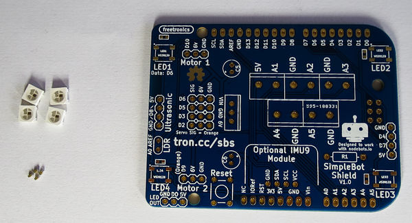
As well as the bare SimpleBot Shield PCB, you will need 4 WS2812B RGB LEDs (the large square packages) and 4 "0603" sized 100nF capacitors (the small rectangular packages).
Tools Required
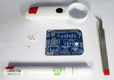
As well as the components, you will need some special tools for SMD assembly:
- Tweezers for placing components
- Liquid solder flux (flux pens are the easiest form of these).
- Some kind of magnification for checking your work (depending on your eyesight you might need something you can solder under, or just a magnifier you can use afterwards).
Soldering Technique
The soldering technique we're going to use is called tack-then-reflow. This means we apply a tiny bit of solder to one pin of each package to hold it in place, then "reflow" solder onto the rest of the pads.
We'll go over the steps of the technique further on, but if you want a preview then Dave Jones' eevblog covers the technique well in this video.
IMPORTANT - WS2812B Orientation
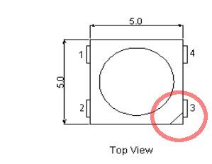
The WS2812Bs have 4 pads that need to be soldered down, numbered 1 through 4. There is a "pin 1" marking on the board. However, the marking on the WS2812B package is not pin 1. It is pin 3.
So when placing the WS2812Bs, make sure that the corner with the triangle marking is diagonally opposite to the pin 1 marking on the board.
Sequence
I recommend doing an LED and a capacitor at a time, moving from corner to corner.
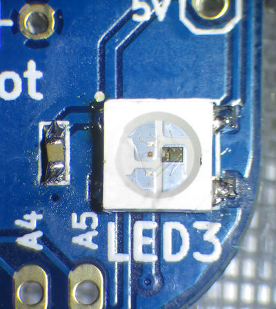
When each corner is done it will look something like this:
Tacking Down
First we "tack" a corner of each component so it can't move. Start by flowing a small amount of solder onto just one bare pad of the capacitor and one pad of the LED, as shown:
Don't apply too much solder, use solder wick to take some off if necessary.
In the picture above I've applied solder to two pads on the left side, because I'm left handed. You can use pads on the right side if you prefer.
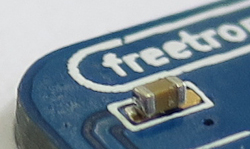
Next, use tweezers to place the capacitor on top of the pads. Hold the capacitor in place with the tweezers in one hand, and use your other hand to bring the soldering iron in to touch the pad where you already placed some solder. As the pad heats the solder will "reflow" up from the pad onto the end of the capacitor:
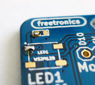
Once the solder cools it "tacks" the capacitor down to the board, so it can't move. Try to bump it with your tweezers, it should stay put.
You may note that in the photo above the solder joint looks particularly poor, it's a "cold" joint and not a lot of solder has flowed up onto the capacitor. This doesn't matter too much at this stage, as long as the capacitor is held in place. We can improve the solder joint later on.
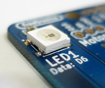
Repeat the "tacking" process with the LED - place the LED on top of its pads, hold it in place with the tweezers in one hand while you heat the pad you presoldered and it solders on to tack it in place. Remember to check the LED orientation before you start soldering!
If either component is soldered a bit crooked, repeat the process (tweezers in one hand, iron in the other) to reflow the solder and move the component into position. It's important you do this now before you try and solder the other pads!
When soldering the LED take special care not to apply too much heat - the green element of the WS2812B is quite heat sensitive and can be damaged if too much heat flows into the LED. You want to remove the soldering iron shortly after the solder becomes molten.
Soldering all pads
Now the LED and the capacitor are held firmly in place, we can solder the other pads. This is now a similar technique to through hole soldering, just using a much smaller amount of solder.
Hold the soldering iron in one hand and plain in the other. Go to each unsoldered pad and heat the joint with the iron, then press a small amount of solder into the joint to solder it.
When soldering the LED, the pad is not particularly exposed so some heat needs can be applied via the leg of the LED itself. Try to heat the pad as much as possible, though - go in at a low angle.
Once the remaining pads are soldered, you may want to revisit the first "tacked" pads and apply a tiny bit more solder so they are more firmly attached.
In the picture above, there's actually a bit too much solder on most of the pads - but it doesn't matter.
Solder remaining corners
Once the first two components are soldered down, repeat for each corner of the shield.
Once the SMD soldering is done, move on to the SimpleBot Shield Assembly step.
