HackCNC Electronics Assembly
The CNCPlotter board designed by Luke Weston for HackCNC uses mostly surface mount parts, but it is provided almost fully assembled so you only need to finish off a few of the easy parts. We could have provided it fully assembled, but then you wouldn't have got to do any soldering, and where's the fun in that!
Before getting started, a quick word about static electricity and how to treat a PCB nicely. You may have heard that electronics is "static sensitive", and that touching the leads of some parts can be enough to kill them. To some extent that's true, and it's a good idea to avoid zapping parts with static electricity if you can. The damage can be subtle and not prevent the part from working initially, but cause it to fail over time, or it could cause immediate failure. However, most electronics is surprisingly robust, particularly once the parts have been fitted to a PCB (printed circuit board). The result is that you should be careful, but not afraid. It's perfectly fine to pick the board up in your hands and touch parts on it, but on the other hand you shouldn't go out of your way to rub it on a polyester jumper or scuff your feet on the carpet and "zap" the board just to see what happens! As long as you're sensible, it'll be fine.
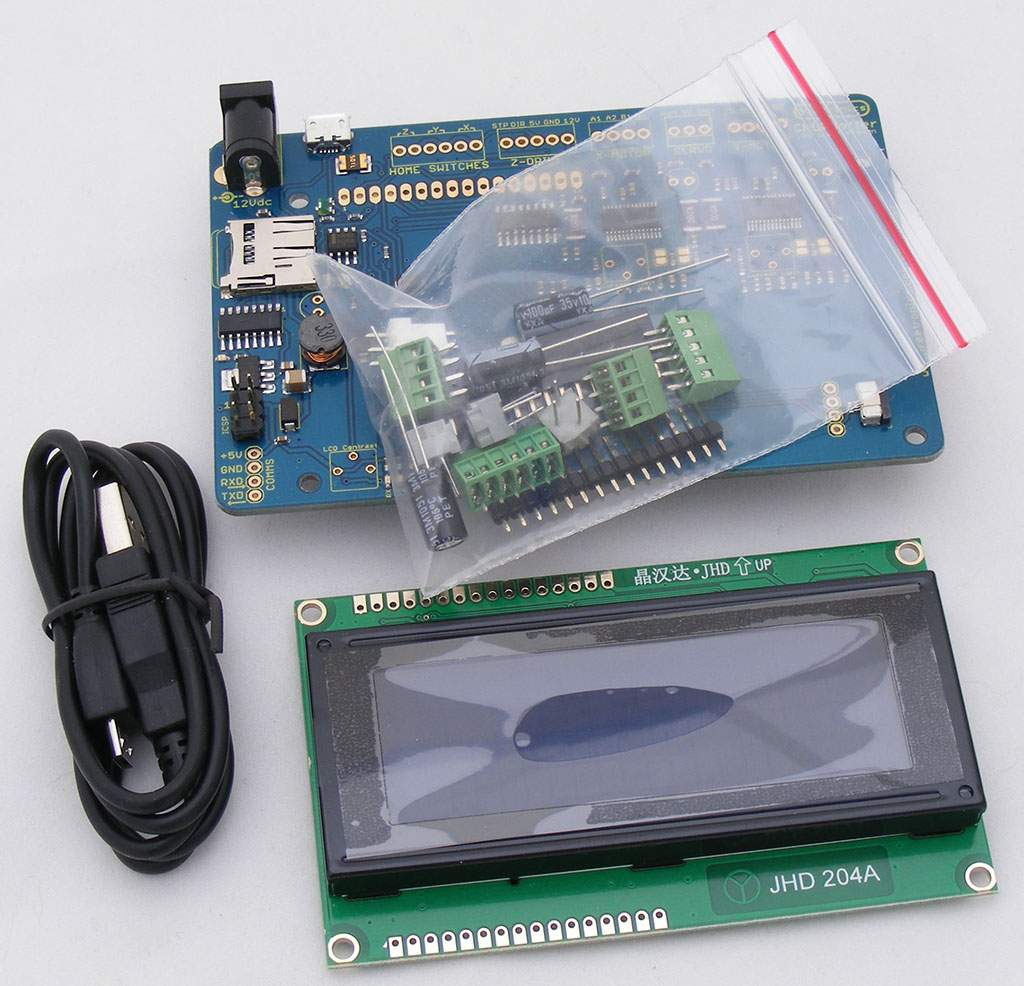
Time for the fun stuff. Your kit of electronic bits should look like this, including the pre-populated PCB, a micro-USB cable, a 20x4 LCD module, and a zip-lock bag of loose parts:
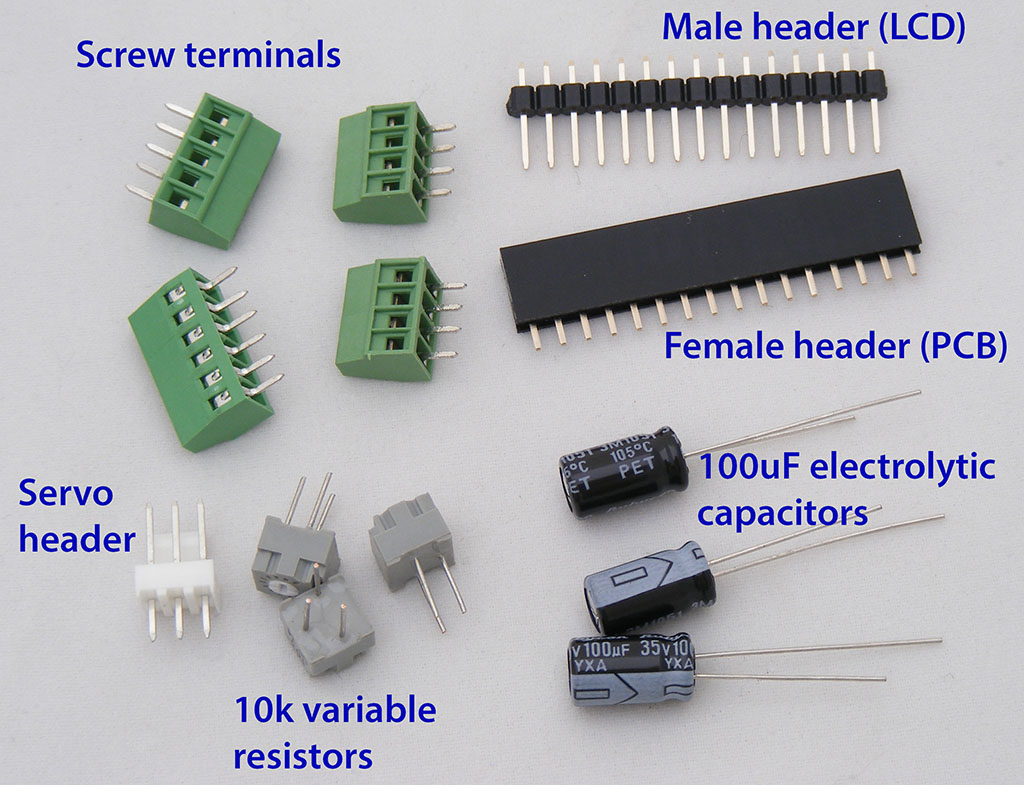
Clear a good spot on your bench, and empty the parts out of the zip-lock bag. Make sure you keep them all together and don't let the capacitors roll off the table. These are the parts you should have:
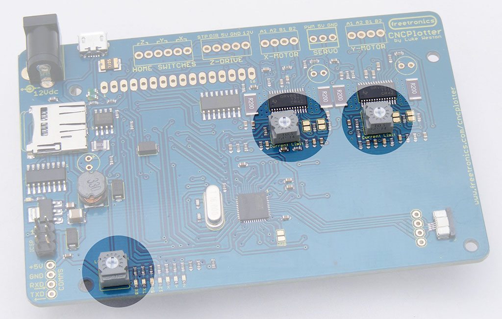
The first parts to install are the square grey variable resistors, commonly referred to as "trimpots".
All three trimpots are the same value so they are interchangeable and you don't need to worry about which one goes where. They have 3 leads laid out in a triangular pattern so that they can only be inserted in the PCB one way around. The leads may end up bent in transit, so bend them straight with your fingers and pop them into place:
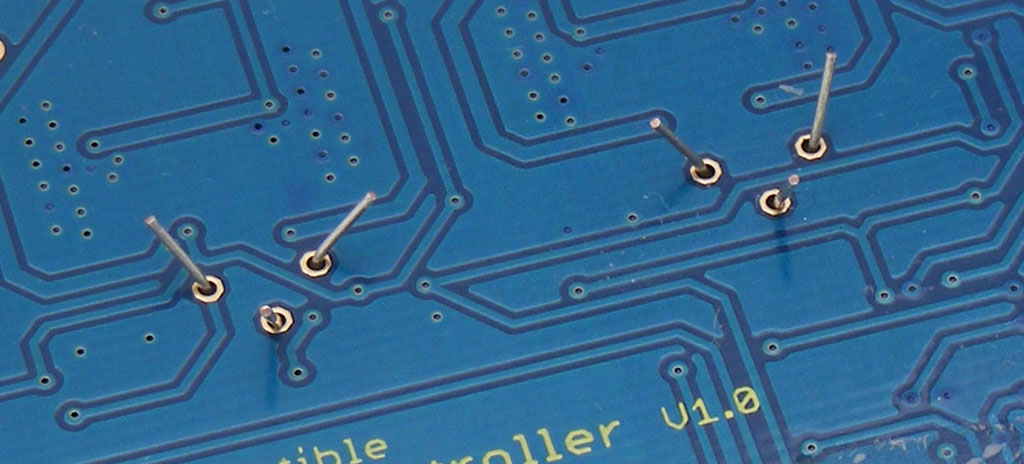
Now if you turn your PCB over to solder them in place, you'll have a problem: the trimpots will probably fall out! The trick is to hold them flush against the board with one hand and gently bend out the leads on the bottom with the other hand, so they end up like this:
Then they'll stay in place with the PCB upside down so you can solder them.


